Engineering Excellence
in Horizontal
Directional Drilling
We are a your specialist engineering design consultancy focused on Horizontal Directional Drilling (HDD)
pipeline projects. Our goal is to promote the use of HDD and advance local industry knowledge in this field.
Who we are
AT CDS HDD DESIGN, we produce market leading design services through our in-depth understanding of the advantages, limitations and risks of this trenchless method. Our team of experienced chartered professional engineers and HDD specialists, offer turnkey design solutions or can tailor a package to suit your requirements.
Featured HDD Services
We know HDD, we understand how the scale of a pipeline
installation impacts drilling rig and plant selection, tooling, fluid design
and methodology. Explore our key services below:
Constructabilty Design Review
We offer peer review of existing HDD designs. This ensures constructability and identifies risks for further consideration.
HDD Alignment Design
The scale of an HDD installation will dictate the plant and equipment used. Our Civil 3D designs consider HDD rig capability and limits.
Geotechnical Investigation Scoping
CDS HDD Design know what geotechnical information influences the drilling process.
Geotechnical Review
Our team have extensive field experience observing how various formations impact the drilling process.
Drilling Fluid Design
We know drilling fluid. From fluid chemistry, contamination, treatment, additive function & concentration, fluid rheology, lab testing and non-Newtonian hydraulics calculations.
All Services
We offer a wide range of solutions from HDD design solutions to tailored
packages to suit your requirements. Trust in our Our team of experienced chartered professional engineers and HDD specialists.
At CDS quality is our priority, and our work speaks for itself.
Ready to get drilling? Get in touch today.
Frequently Asked Questions
Yes, this is common for HDD installations but don't attempt an installation at the minimum bend radius of the pipe material. It will be the drill pipe and ground conditions that dictate achievable bend radii.
Hydro-fracture is where the drilling fluid pressure exerted against the borehole wall exceeds the fracture pressure of the formation soil or rock being drilled. At this point fluid will migrate from the borehole potentially causing infrastructure or environmental damage. Fracture pressure is a function of formation cohesion, friction angle, Poisson’s Ratio, Elastic Modulus and Effective Stresses along the bore path. Once fracture pressures are determined they can then be checked against the downhole drilling fluid pressures along the bore path. Downhole pressure is a function of hydro-static fluid pressure, and the annular pressures losses required to circulate the non-Newtonian drilling fluid for a given velocity.
Yes, unlike water which has the same viscosity at different shear rates, drilling fluids are designed to be a non-Newtonian fluid. This means the viscosity changes depending on the shear rate or velocity applied to the fluid. Because of this, when we run our hydraulics calculations, we need to consider the various geometries the fluid will pass through and what the fluid viscosity will be for the resulting velocity.
In New Zealand Polyethylene Pipe specifically PE100 SDR11 pipe is the most commonly installed pipe material. In some applications steel and uPVC it also used. The pipe is installed in tension so must be jointed to allow for this.
Yes and this is relatively common in New Zealand and Australia. But consideration should be given to the risk of not meeting required tolerances for lower grade installations. Where low grades are to be drilled with HDD good geotechnical information and a contractor with a track record of achieving the design grades will reduce risk.
Yes, this type of HDD installation is becoming more common. Due to the elevated risk profile for these pipe crossings, the scope of geotechnical investigations must be well defined to ensure relevant information is captured. Surface location of the downhole transmitter is often not possible during drilling of the pilot hole. As a result, magnetic survey tools are usually used. This requires a surveyed wire grid or beacon at surface through which an electrical current is run to generate a magnetic field. The position of the downhole orientation tool can then be surveyed relative to this magnetic field. Gyro tools are also now becoming more common to survey the pilot hole. The benefit of a gyroscope is that is not impacted by magnetic interference.
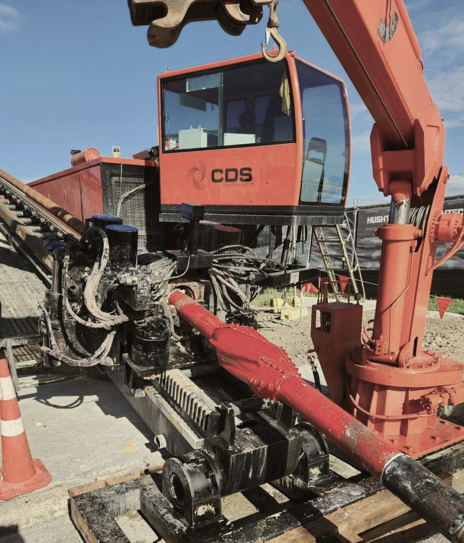
The pilot hole is arguably the most important phase of the HDD process. During drilling of the pilot hole, drill pipe sting is progressively made up on the rig with threaded joints and run into the hole. A drill bit at the leading end of the drill pipe string is navigated along the design alignment. While the pilot hole is progressed drilling fluid is pumped down the drill pipe and through nozzles in the bit where it mixes with drill cuttings. Drill solids removed by the bit are transported back along the annular space between the borehole walls and drill pipe to surface. The annular space is a result of the drill bit being larger than the diameter of the drill pipe. During drilling of the pilot hole, the position of the drill string is surveyed, and adjustments are made to keep the drill bit on the design alignment. Downhole fluid pressures are highest during drilling of the pilot hole so the risk of hydro-fracture must be closely managed. After the pilot hole is complete, the bore hole is usually upsized in the reaming phase to accommodate the product pipe diameter.
Have questions about a job?
Give our team a call
